Welcome to the official website of Shenzhen Zhihuang Technology Co., Ltd.!

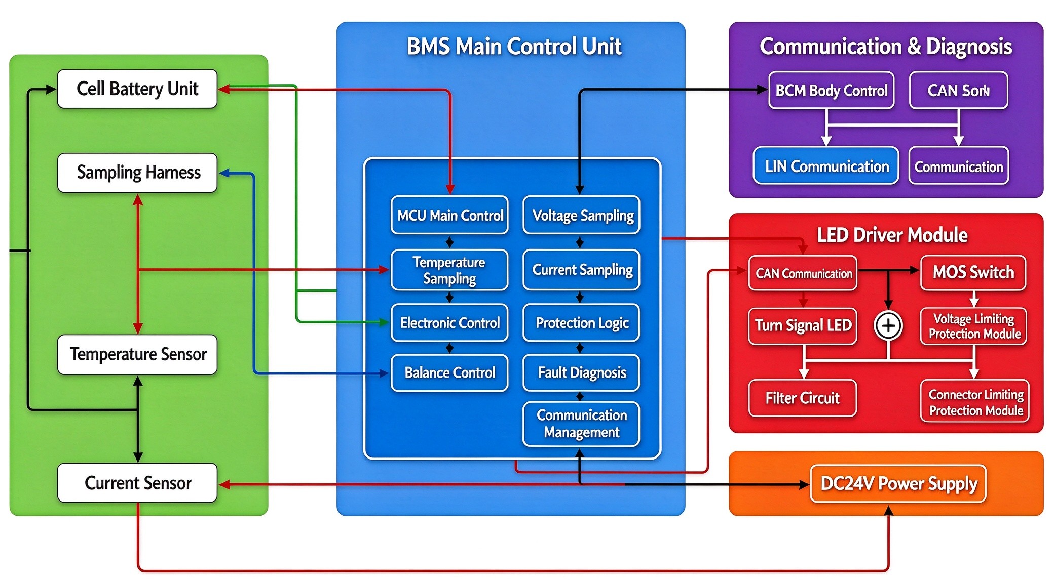
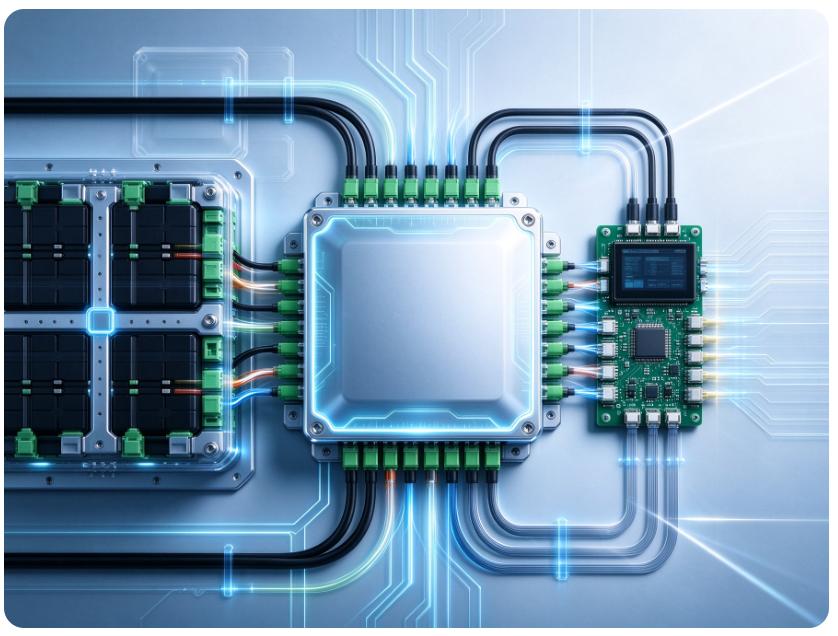
This architecture is centered around the BMS control unit, which builds a complete closed-loop system for battery sensing acquisition, algorithm decision-making, safety protection, peripheral driving, and vehicle communication, achieving full lifecycle monitoring and intelligent control of the battery. The entire BMS system covers four core capabilities: signal acquisition, balanced management, safety protection, and communication interaction. It monitors the battery status in real-time, avoids risks such as overvoltage, overcurrent, and high temperature, and ensures the safe, efficient, and stable operation of the battery system.
Single cell battery unit (sensing acquisition layer): The front-end sensing network is composed of battery cells, sampling harnesses, temperature sensors, and current sensors. Real time collection of individual cell voltage, circuit current, and multi-point temperature of battery pack to obtain basic state data of battery cells, providing raw signals for BMS main control operation.
BMS main control unit (core decision-making layer): The system computing center integrates MCU main control, multi-channel sampling, equalization control, protection logic, fault diagnosis, and communication management functions. Process and analyze collected signals, complete SOC estimation, automatically perform cell balancing, ensure battery consistency, monitor abnormal operating conditions, trigger safety protection, and complete fault identification and reporting.
Communication and Diagnosis (Vehicle Interaction Layer): Adopting a CAN+LIN dual bus architecture, it is interconnected with the BCM body controller. The CAN bus transmits battery status, fault information, and vehicle control commands at high speed, while the LIN bus supports low-speed device communication, system calibration, and fault diagnosis, achieving cross module collaboration.
LED driver module (execution driver layer): receives main control commands, drives the turn signal LED through CAN communication, and relies on MOS transistors to achieve circuit on/off control. Matching filtering capacitors, limit code modules, and connector terminals to suppress electromagnetic interference and ensure stable and reliable power circuits.
DC24V power supply (system power supply layer): provides stable 24V working power supply for BMS main control, sensors, communication chips, and drive modules, ensuring the continuous and reliable operation of the entire control system.
Tel: 0755-85280120
Email: georgeguan@goldone.com.cn
Head Office: Building 4, Room 505, Qianhai Kexing Science Park, Bao'an District, Shenzhen
Factory Address: 4/F, Building A1, Langxin Industrial Zone, Langxin Community, Shiyan Street, Bao'an District, Shenzhen